
Managing Kitchen Greywater Challenges requires an advanced understanding of hydrological loads; thermal inertia; and the complex chemical interactions of fats, oils, and grease (FOG). This technical domain addresses the architectural failure points where commercial kitchen effluent transitions from a high-velocity pressurized system to a gravity-fed waste stream. The primary challenge lies in the high organic payload and thermal volatility of the effluent, which can lead to system-wide latency or complete infrastructure failure if not managed through a robust separation and treatment stack. Because greywater contains significant concentrations of pathogens and colloidal solids, the solution must provide total encapsulation of the waste stream to prevent environmental contamination. Effective management functions as a critical layer in the building’s infrastructure, ensuring that the waste-to-drain throughput remains consistent while minimizing the overhead associated with mechanical maintenance. This manual defines the operational parameters for integrating high-capacity grease interceptors and enzymatic treatment units into modern facility frameworks.
TECHNICAL SPECIFICATIONS
| Requirement | Operating Range | Protocol/Standard | Impact Level | Material/Resource Grade |
| :— | :— | :— | :— | :— |
| Inlet Temperature | 40C to 80C | ASME A112.14.3 | 9 | High-Density Polyethylene (HDPE) |
| Influent Loading (FOG) | 100 to 5,000 mg/L | PDI G-101 | 10 | 304/316 Stainless Steel |
| Effluent pH Level | 6.0 to 9.5 pH | EPA Method 150.1 | 7 | Real-time Bio-Sensing Array |
| Flow Rate (Throughput) | 20 to 500 GPM | NSF/ANSI 44 | 8 | Schedule 80 PVC / Cast Iron |
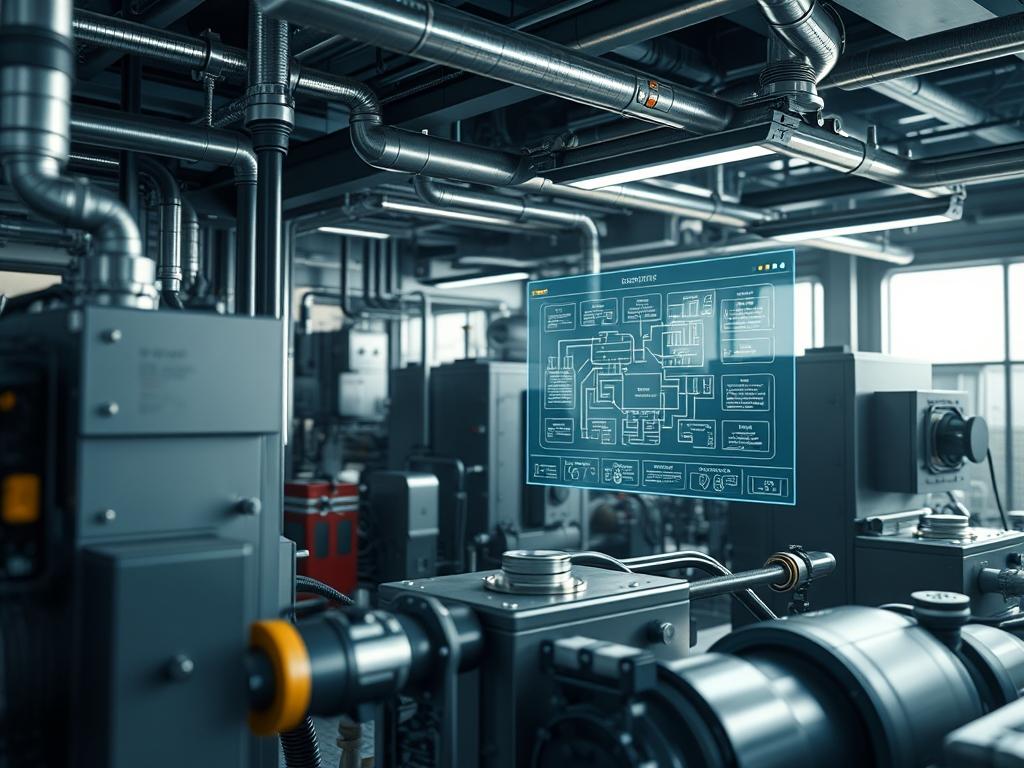
| Control Logic Voltage | 120V/240V AC | NEC Article 430 | 6 | PLC with Modbus/TCP support |
| Storage Capacity | 500 to 15,000 Gal | IAPMO Z1001 | 9 | Reinforced Concrete or FRPI |
THE CONFIGURATION PROTOCOL
Environment Prerequisites:
Before initiating the deployment, verify that the physical site meets the following requirements:
1. Compliance with ASME A112.14.4 for automatic grease removal devices.
2. Installation of a Backflow Preventer (BFP) on all clean water supply lines to the dosing unit.
3. Network access via RJ45 or 802.11ac for monitoring PLC-driven sensors if remote telemetry is required.
4. Correct pipe sizing to ensure a minimum velocity of 2 feet per second to prevent solid settlement.
5. User permissions must be set to “Level 3 – Administrator” for any interface with the Building Management System (BMS).
Section A: Implementation Logic:
The engineering design relies on the principle of differential specific gravity. Since grease is less dense than water, it exhibits a natural buoyancy. However, Kitchen Greywater Challenges are compounded by thermal-inertia: hot water keeps grease in an emulsified state, preventing separation. The system architecture must facilitate “thermal stalling” to allow the liquid to cool, thereby increasing the separation efficiency. Additionally, the configuration uses idempotent enzymatic dosing to catalyze the breakdown of lipids at the molecular level. This encapsulation of the grease ensures it does not reform in the downstream piping, reducing the risk of “fatbergs” in the municipal sewer system. The logic is predicated on maximizing residence time while maintaining high throughput.
Step-By-Step Execution
1. Primary Interceptor Calibration
Calibrate the static or automatic grease interceptor to match the peak concurrency of all kitchen fixtures. Access the unit and verify the position of the Flow Control Valve (FCY).
System Note: This action regulates the influent velocity into the primary chamber. Adjusting the FCY ensures that the “packet-loss” of grease particles into the effluent stream is minimized by keeping the turbulence below the Reynolds threshold for laminar flow.
2. Enzymatic Injector Programming
Configure the Dosing Pump Controller to release biological catalysts during periods of low hydraulic load. Use the command SET_INTERVAL_600 for a ten-minute cycles or utilize the Proportional-Integral-Derivative (PID) loop settings on the PLC for real-time load matching.
System Note: Dosing during low-flow periods increases the residence time of the enzymes within the Interceptor Core. This ensures an idempotent chemical reaction where the biological payload successfully degrades the FOG layer without being flushed out by high-velocity effluent.
3. Thermal Sensor Alignment
Install the Pt100 RTD Sensors at the inlet and outlet ports of the grease trap. Map these sensors to the BMS via the Modbus Register 40001.
System Note: Monitoring the thermal gradient is essential. If the delta between the inlet and outlet is too small, the grease is failing to reach its “congealing point,” indicating that the system throughput is exceeding its capacity and causing thermal bypass.
4. Solids Filtration Scrubber Setup
Activate the secondary filtration stage by initializing the Mechanical Solids Scrubber (MSS). Verify the filter mesh is seated and that the Differential Pressure Sensor (DPS) is zeroed.
System Note: High solids content increases the overhead on the grease separation process. The MSS acts as a hardware-level firewall, removing physical debris that would otherwise increase the density of the grease layer and prevent efficient buoyancy-based separation.
Section B: Dependency Fault-Lines:
Software or mechanical failures often stem from sensor fouling, also known as “signal-attenuation.” If the grease layer coats the ultrasonic level sensors, the system will report a “false-empty” state. To mitigate this, ensure the Self-Cleaning Sensor Nozzle is active and connected to a high-pressure water line. Another common bottleneck is the “emulsification loop” where high-speed dishwashing pumps create a stable emulsion that defies gravity separation. In these cases, a chemical de-emulsifier must be added to the sequence of operations.
THE TROUBLESHOOTING MATRIX
Section C: Logs & Debugging:
When a fault occurs, check the System Error Log located at /var/log/greywater_controller.log or examine the physical status LEDs on the control panel.
- Error Code E10 (High Turbidity): This suggests a failure in the filtration mesh or an over-limit organic payload. Inspect the Mesh Screen for tears and verify that the influent FOG concentration does not exceed the rated 5,000 mg/L.
- Error Code E22 (Pump Cavitation): This indicates air ingress or a suction-side blockage. Check all NPT fittings for leaks and ensure the Suction Strainer is not occluded by solidified lipids.
- Visual Cue (Methane Odor): If H2S or CH4 levels rise, it indicates anaerobic conditions due to excessive solids buildup. Increase the frequency of the Sludge Removal Cycle and verify the status of the Ventilation Stack.
- Packet-Loss (Grease Bypass): If grease is detected in the final effluent sample, check the Inlet Baffle for erosion. A compromised baffle causes short-circuiting, where the influent skips the separation chamber entirely.
OPTIMIZATION & HARDENING
Performance Tuning:
To increase throughput without sacrificing separation efficiency, implement a multi-stage “parallel processing” architecture. By splitting the effluent stream into two smaller interceptors, you increase the surface area for separation. Use a Load Balancer Valve to ensure equal distribution: this prevents one unit from reaching its thermal-capacity while the other remains underutilized.
Security Hardening:
Physical security is as critical as digital logic. Ensure all interceptor manholes are secured with Tamper-Proof Bolts and that the PLC Control Cabinet is locked with a “Class A” enclosure. On the digital side, change default credentials on the Modbus TCP Interface to prevent unauthorized modification of the dosing intervals. Implement a Fail-Safe Physical Logic that closes the main outlet valve if the secondary containment sensor detects a breach.
Scaling Logic:
As the facility grows, the system must scale vertically or horizontally. Vertical scaling involves replacing existing components with higher-grade materials: such as upgrading from PVC to Cast Iron to handle higher thermal loads. Horizontal scaling involves adding modular “Treatment Pods” in series. The system logic should be designed to auto-discover new nodes on the RS-485 bus to maintain a unified administrative view of the greywater health.
THE ADMIN DESK
How do I clear a “High Grease Level” alarm quickly?
Manually initiate the Skimmer Cycle via the control override. If the alarm persists, verify the sensor is not fouled. Use a non-polar solvent to clean the sensor head and restart the PLC Service to clear the cached fault state.
Why is the enzymatic dosing pump not running?
Check the Fluid Level Sensor in the chemical reservoir. If the reservoir is empty, the software triggers an idempotent lockout to prevent the pump from running dry. Top off the enzymatic payload and reset the Dosing Register.
What causes frequent “Downstream Blockage” alerts?
This is typically caused by “re-emulsification,” where FOG particles recombine in the pipes. Ensure the effluent temperature is below 35C before it exits the final stage. You may need to increase the Cooling Loop cycle or the enzymatic concentration.
How often should I audit the physical filter mesh?
Perform a manual inspection every 30 days or when the Differential Pressure (DP) across the filter exceeds 5 PSI. High throughput environments with high solids payloads may require a weekly audit to maintain maximum flow efficiency and prevent overflow.
Can I integrate this system with an existing Siemens or Honeywell BMS?
Yes. Most modern controllers support Modbus or BACnet protocols. Map the device IP Address into your building network and use the vendor-provided GSD/JSON files to populate the data points within your central monitoring dashboard.