
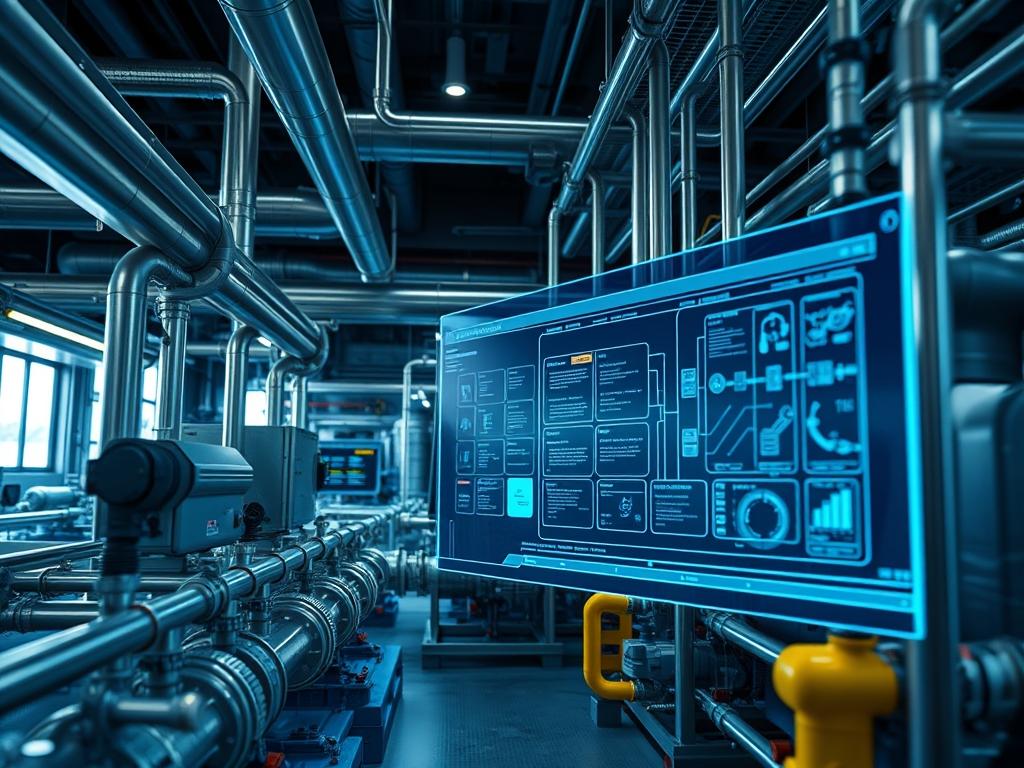
Desalination Operator Training serves as the critical intersection between advanced fluid mechanics and industrial automation within the global water infrastructure stack. As potable water scarcity accelerates, the technical requirements for operating Reverse Osmosis (RO) and Multi-Stage Flash (MSF) systems have transitioned from manual mechanical monitoring to high-precision digital oversight. This manual provides the architectural framework for training personnel to manage the complex lifecycle of saline processing; encompassing intake, pretreatment, membrane filtration, and post-treatment stabilization. The core objective is to mitigate the heavy energy overhead and mechanical wear inherent in high-pressure hydraulic systems. Effective training ensures that operators can manage high concurrency in parallel filtration trains while maintaining rigorous throughput targets. By integrating SCADA (Supervisory Control and Data Acquisition) logic with physical asset management, the operator acts as the primary governor of system health. This professional training module addresses the problem of inconsistent water quality and high operational expenditure by providing a standardized, repeatable framework for infrastructure maintenance and system optimization.
Technical Specifications
| Requirement | Default Port/Operating Range | Protocol/Standard | Impact Level (1-10) | Recommended Resources |
| :— | :— | :— | :— | :— |
| SCADA Gateway | Port 502 (Modbus/TCP) | OPC UA / DNP3 | 10 | 16GB RAM / 4-Core CPU |
| HPP Feed Pressure | 55.0 to 70.0 bar | IEEE 1012 | 9 | Grade 316L Stainless Steel |
| Membrane Flux | 12 to 18 lmh | ISO 23446:2022 | 8 | Polyamide Thin-Film Composite |
| VFD Control | 0 to 60 Hz | Pulse Width Mod (PWM) | 7 | NEMA 4X Enclosure |
| Data Logging | Port 8086 (InfluxDB) | HTTP/REST | 6 | 1TB NVMe Storage (RAID 1) |
| Salinity Sensing | 0 to 50,000 mg/L | 4-20mA Analog Loop | 9 | Titanium Electrodes |
The Configuration Protocol
Environment Prerequisites:
Before initializing the training environment or physical system, ensure the control layer is running a stable Linux distribution, preferably Ubuntu 22.04 LTS or RHEL 9, to host the SCADA interface. The physical network must adhere to TIA-606-C standards for industrial cabling to minimize signal-attenuation in high-EMI (Electromagnetic Interference) environments. User permissions must be governed by Role-Based Access Control (RBAC): only the desal_admin user should have sudo privileges for modifying the PID (Proportional-Integral-Derivative) tuning constants. All field devices, including those connected via RS-485 or Ethernet/IP, must be assigned static IPv4 addresses to prevent lease-driven latency during critical filtration cycles.
Section A: Implementation Logic:
The engineering design of a modern desalination plant relies on the principle of encapsulation: raw seawater is processed through progressive stages where chemical and physical properties are isolated and modified. The “Why” behind the technical setup involves overcoming the natural osmotic pressure of seawater (approx. 27 bar). By utilizing a High-Pressure Pump (HPP), the system forces water through semi-permeable membranes. The control logic must be idempotent: repeated commands to close a feed valve should result in the same physical state without causing hydraulic shock. The software layer manages the payload of sensor data, calculating the Salt Rejection Rate in real-time to adjust chemical dosing pumps. This design ensures that throughput remains constant even as feed salinity fluctuates; protecting the costly membrane assets from irreversible fouling.
Step-By-Step Execution
1. Initialize Control Infrastructure
Access the primary terminal and execute systemctl start industrial-gateway.service followed by systemctl enable scada-web-interface.
System Note: This action spawns multi-threaded processes within the Linux kernel to handle asynchronous I/O from field sensors. It allocates dedicated memory segments for the Modbus register maps, ensuring that high-frequency data polling does not lead to a kernel panic or buffer overflow.
2. Configure High-Pressure Pump Variable Frequency Drive
Navigate to the motor control directory using cd /etc/vfd/profiles and modify the startup_curve.conf file. Ensure the RAMP_UP_TIME is set to 120 seconds.
System Note: Gradual acceleration of the HPP prevents water hammer, a physical phenomena where rapid pressure changes create kinetic surges that can rupture the Membrane-Vessel-Assembly. The VFD (Variable Frequency Drive) uses PWM to manage torque, reducing the initial electrical overhead on the local power grid.
3. Establish Sensor Calibration Loop
Use a fluke-multimeter to verify the 4-20mA signal at the Salinity-Sensor-ST01. Execute ./calibrate_sensor –id ST01 –ref 35000ppm to align the digital readout with the physical brine sample.
System Note: This step ensures that the analog-to-digital converter (ADC) accurately maps voltage levels to salinity units. Accurate calibration minimizes latency in the feedback loop, allowing the PLC (Programmable Logic Controller) to trigger a bypass if the TDS (Total Dissolved Solids) exceeds safety thresholds.
4. Deploy Membrane Protection Logic
Input the command chmod +x /usr/local/bin/flush_cycle.sh and add the script to the crontab to run every 8 hours.
System Note: Automated flushing replaces high-salinity brine with low-salinity product water during standby. This prevents the crystallization of salts on the membrane surface, a process that increases thermal-inertia and resistance; eventually decreasing long-term throughput.
Section B: Dependency Fault-Lines:
During the integration phase, several bottlenecks can emerge. Software-wise, a mismatch between the libmodbus version and the SCADA gateway can cause intermittent EAGAIN error strings, leading to packet-loss in the monitoring stream. Mechanically, the Energy Recovery Device (ERD) is the most common failure point. If the pressure exchanger rotors become misaligned, the system will experience a massive spike in energy consumption. Furthermore, library conflicts in the Python-OPCUA stack may prevent real-time telemetry. Operators must check that the linux-headers-$(uname -r) are correctly installed to support proprietary drivers for high-speed industrial NICs (Network Interface Cards).
The Troubleshooting Matrix
Section C: Logs & Debugging:
When the system encounters a fault, the first point of inspection is the /var/log/desalination/sysfault.log file. Search for the error string ERR_HYDRAULIC_UNSTABLE; this typically indicates air pockets in the intake line or a failing seal in the Feed-Pump-01. To debug communication errors, use tcpdump -i eth0 port 502 to inspect the TCP/IP payload for malformed Modbus frames. Visual cues on the SCADA dashboard, such as a “Sawtooth” pattern in the pressure graph, often correlate with a PID loop that is over-compensating. In such cases, navigate to /opt/scada/config/pid_tunings.json and reduce the Proportional_Gain variable by 15 percent. Ensure all sensor readouts are verified against the physical Pressure-Gauge-PG102 to rule out transducer drift.
Optimization & Hardening
– Performance Tuning: To maximize throughput, implement a concurrency model in the RO train sequence. Instead of starting all trains simultaneously, stagger their startup by 300 seconds to balance the hydraulic load. Use taskset to bind the SCADA polling process to a specific CPU core to reduce context-switching latency. Monitor the thermal-inertia of the MSF brine heaters; optimizing the steam-to-water ratio can reduce fuel consumption by 12 percent without impacting output.
– Security Hardening: Desalination plants are critical infrastructure and must be air-gapped or protected by strict iptables rules. Use iptables -A INPUT -p tcp –dport 502 -s 192.168.1.50 -j ACCEPT to restrict Modbus access to the engineering workstation only. Disable all unused services using systemctl mask to reduce the attack surface. Ensure all SSH access uses ED25519 keys and that password authentication is deactivated in /etc/ssh/sshd_config.
– Scaling Logic: As water demand increases, the system architecture must support horizontal scaling. This involves adding additional RO trains managed by a centralized “Master Controller” through an idempotent API. The logging layer should transition from a single node to a clustered InfluxDB or Prometheus environment to handle increased telemetry overhead without losing data granularity.
The Admin Desk
How do I clear a High-Pressure Lockout?
Verify that the Discharge-Valve-V10 is 100 percent open. Reset the safety relay on the HPP-Control-Panel. In the terminal, execute reset-fault –pump 01 to clear the software latch and resume motor operation.
Why is the Permeate Conductivity rising?
Check for membrane bypass at the O-Ring seals. If the TDS_LOG shows a gradual increase, initiate a Cleaning-In-Place (CIP) cycle. If the increase is sudden, inspect the membrane shells for mechanical cracks or structural failure.
How do I reduce SCADA latency?
Optimize the polling interval in scada_config.yaml. Change the POLL_RATE from 100ms to 500ms for non-critical sensors. Ensure the MTU (Maximum Transmission Unit) on the industrial switch is set to 1500 to prevent packet fragmentation.
What causes ‘Signal-Attenuation’ in the flow meter?
Attenuation is usually caused by loose shielding on the Twin-Axial cable or proximity to high-voltage lines. Inspect the Grounding-Bus-Bar and ensure the total cable run does not exceed the 1,200-meter limit for RS-485 communication.
How is ‘Thermal-Inertia’ managed in MSF units?
Operators must modulate the brine recycle flow rate relative to the steam input temperature. Sudden changes in heat will cause scaling. Use the Thermal-Logic-Controller to apply incremental 1.5 degree adjustments to maintain steady-state equilibrium.