
Industrial Bag Filter Housing Selection constitutes a critical intersection between mechanical fluid dynamics and digital process control within modern industrial stacks. In sectors such as petrochemical refining, high-volume water treatment, and modular energy infrastructure, the filtration housing acts as the primary encapsulation layer for fluid purification. This selection process is not merely a hardware procurement task; it is a complex architectural decision that dictates the throughput and latent reliability of the entire fluid processing pipeline. System architects must treat the housing as a high-pressure node where the payload consists of process liquids and the overhead is measured in differential pressure. A failure in selection leads to catastrophic signal-attenuation in sensor accuracy or physical breach of the containment vessel. By standardizing the selection protocol, engineers ensure that the installation is idempotent; each deployment across a distributed infrastructure must yield identical performance characteristics regardless of local environmental variables. This manual provides the technical framework for selecting, configuring, and auditing these essential assets.
Technical Specifications
| Requirement | Default Port/Operating Range | Protocol/Standard | Impact Level (1-10) | Recommended Resources |
|———————————|——————————|——————-|———————|———————————–|
| Vessel Pressure Rating | 150 to 300 PSI | ASME Section VIII | 10 | SA516 Grade 70 Carbon Steel |
| Fluid Throughput | 50 to 4500 GPM | ISO 2186 | 9 | 316L Stainless Steel Shell |
| Seal Integrity | -20 to 200 Celsius | ASTM D2000 | 8 | Viton or EPDM Mechanical Seals |
| Data Monitoring | 4-20mA Analog / Modbus TCP | IEEE 802.3ad | 7 | PLC with 24V DC Power Supply |
| Particulate Payload Capacity | 1 to 200 Microns | Beta Ratio 1000 | 8 | Reinforced Mesh Support Baskets |
| Hardware Connection | 2 inch to 12 inch Flange | ANSI/ASME B16.5 | 6 | High-Tensile Zinc Plated Bolts |
THE CONFIGURATION PROTOCOL
Environment Prerequisites:
Successful integration of an industrial filter housing requires strict adherence to international engineering standards and local regulatory frameworks. The facility must comply with ASME B31.3 for process piping and NEC Class 1, Division 2 if the fluid payload is volatile. All installation personnel must hold valid Pipefitter Level 4 certifications and possess administrative rights to the SCADA (Supervisory Control and Data Acquisition) interface. Hardware dependencies include calibrated DP (Differential Pressure) transmitters, isolation valves with a minimum ANSI Class 300 rating, and a centralized logic-controller for real-time telemetry ingestion.
Section A: Implementation Logic:
The engineering logic behind Bag Filter Housing Selection rests on the principle of minimizing hydraulic overhead while maximizing particulate capture. We view the housing as a stateful container in a fluid network. The inner chamber provides the encapsulation for the filter element, which functions as the processing logic. As fluid moves through the media, the pressure drop represents the computational cost of the operation. We must account for thermal-inertia; the heavy metallic mass of the housing retains heat, which can affect the viscosity of the fluid and, consequently, the flow throughput. If the housing is undersized, the resulting concurrency of particles at the media surface leads to a rapid spike in differential pressure, effectively causing a system-level denial of service for fluid movement.
Step-By-Step Execution
1. Structural Integrity and Material Validation
Verify the metallurgical composition of the housing using a spectrometer to ensure compliance with the bill of materials. The shell must be inspected for uniform thickness using an ultrasonic thickness gauge.
System Note: This action ensures that the physical kernel of the filtration system can withstand the cyclic stress of high-pressure pulses. Inaccurate material grading leads to stress corrosion cracking, which compromises the encapsulation of the process fluid.
2. Seal Seating and Elastomer Calibration
Apply a thin layer of system-compatible lubricant to the O-ring and seat it within the machined groove of the housing head. Tighten the swing-bolt closures in a star pattern using a torque wrench calibrated to the manufacturer specifications.
System Note: Proper seal compression is essential for maintaining a high-fidelity environment. An improper seal introduces bypass leakage, allowing unfiltered payload to contaminate the downstream stack, mimicking the effect of a data leak in a digital architecture.
3. Differential Pressure Sensor Integration
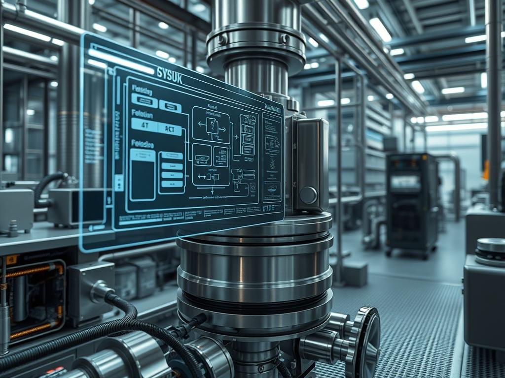
Connect the high-side and low-side ports of the DP transmitter to the upstream and downstream taps of the housing respectively. Wire the transmitter to the PLC (Programmable Logic Controller) using shielded twisted-pair cabling to prevent signal-attenuation.
System Note: The sensor provides the primary telemetry for the system. The logic-controller monitors the 4-20mA loop. Any interruption in this signal is treated by the system as a critical failure, triggering a fail-safe shutdown of the feed pumps.
4. Priming and Air Evacuation
Slowly open the inlet valve while keeping the vent valve at the top of the housing open. Close the vent valve only once a steady stream of fluid is observed, ensuring all air is purged from the chamber.
System Note: Removing air pockets is vital to prevent water hammer. Air in the system creates compressibility issues that lead to erratic pressure readings and high latency in flow response.
5. Flow Rate Hardening and Baseline Testing
Bring the system to full operational flow and record the initial differential pressure. This value represents the clean-filter baseline or the “null state” of the housing.
System Note: Establishing a baseline is crucial for predictive maintenance. Significant deviations from this baseline during startup indicate a mechanical bottleneck or a configuration error in the piping header.
Section B: Dependency Fault-Lines:
The primary bottleneck in filter housing performance is the mismatch between fluid viscosity and the micron rating of the bag. High-viscosity fluids exhibit increased friction against the housing walls, leading to higher thermal-inertia. Furthermore, if the support basket is not perfectly aligned, the bypass-seal will fail, a condition known as “encapsulation breach.” In automated systems, dependency failures often occur at the junction between the physical sensor and the digital bus. If the Modbus TCP gateway experiences high packet-loss, the system may fail to report a clogged filter, leading to a physical rupture of the filter bag due to excessive pressure.
THE TROUBLESHOOTING MATRIX
Section C: Logs & Debugging:
When a fault occurs, technicians must first consult the HMI (Human Machine Interface) logs for specific error strings. Common codes include ERR-DP-HIGH (Differential Pressure Limit Reached) and ERR-SIG-LOW (Sensor Loop Open).
1. Check for Signal-Attenuation: If the DP readings are fluctuating wildly, inspect the sensor wiring for proximity to high-voltage lines. Use a fluke-multimeter to verify the 24V power supply stability.
2. Analyze Physical Log Cues: Inspect the vent valve for evidence of bypass. If fluid is found in the “clean” side of the housing during a filter change, the internal basket seal is the primary suspect.
3. Audit Throughput Latency: If the flow rate is lower than the pump curve suggests, check for obstruction at the inlet nozzle of the housing.
4. Thermal-Inertia Verification: Use an infrared thermal imager to look for cold spots on the housing surface during heated fluid processing. Cold spots indicate stagnant zones where fluid is not circulating, reducing the effective volume of the encapsulation.
OPTIMIZATION & HARDENING
– Performance Tuning: To maximize throughput, architects should implement a multi-bag housing configuration. This allows for parallel processing of the fluid stream, increasing the concurrency of filtration and reducing the individual flow velocity through each bag. This lower velocity reduces the pressure overhead and extends the lifecycle of the filter media.
– Security Hardening: Physical security of the housing involves the use of safety interlocks. These mechanical devices prevent the housing from being opened while under pressure. On the digital side, harden the PLC by disabling unused ports and implementing a robust firewall between the industrial control network and the corporate LAN to prevent unauthorized modification of pressure setpoints.
– Scaling Logic: When scaling the filtration stack, utilize a “Header-and-Branch” architecture. By placing multiple housings in a parallel array, you can take individual units offline for maintenance without impacting the overall system availability. This redundant design ensures that the system can handle surges in particulate payload without a total stop in production.
THE ADMIN DESK
How do I detect a bypass leak early?
Monitor the downstream turbidity levels. A sudden drop in differential pressure accompanied by a spike in downstream particulate counts indicates a bypass-seal failure. The system should be halted immediately to replace the internal O-ring and inspect the support basket alignment.
What causes frequent signal-attenuation in DP sensors?
This is typically caused by moisture ingress in the sensor housing or poor grounding of the shielded cable. Ensure all conduit seals are tight and use a dedicated ground bus for all 4-20mA instrumentation to maintain signal integrity.
How does thermal-inertia impact startup times?
In high-temperature applications, the housing acts as a heat sink. The system will experience high viscosity and reduced throughput until the metal reaches thermal equilibrium with the fluid. Use external insulation jackets to minimize this latency and stabilize the process.
Can I run the system if the PLC reports packet-loss?
No. Packet-loss in the monitoring network means the system is “blind” to pressure spikes. Operating without real-time telemetry risks a mechanical failure of the housing or downstream equipment. Troubleshoot the Ethernet switch or cables before resuming flow operations.
Is it possible to automate bag change-out cycles?
While the physical bag change is manual, the decision-making can be automated. Set the PLC to trigger an alarm and divert flow to a standby housing when the differential pressure reaches 15 PSI above the baseline.