
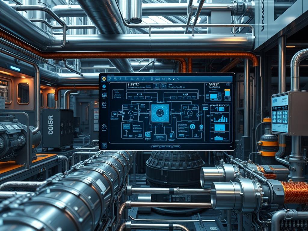
Remote Desalination Hubs (RDHs) represent a critical convergence of hydraulic engineering and edge computing infrastructure. These systems provide decentralized water purification by processing saline or brackish feed-stocks in environments where centralized utilities are non-existent. Within the broader technical stack; the RDH operates as an autonomous edge node. It integrates renewable energy harvesting with high-pressure fluid dynamics and real-time telemetry. The primary problem addressed is the high energy-cost of traditional desalination; the solution provided by RDHs involves localized, smart-grid-aware processing that minimizes energy overhead through variable-frequency optimization. As an architect; one must treat the water output as the primary payload and the brine waste as a manageable system overhead. This manual outlines the deployment of these hubs; emphasizing the synchronization of mechanical assets with digital control planes to ensure high throughput and system longevity. By treating the hydraulic process as an idempotent set of operations; we ensure that the system remains resilient against power fluctuations and intermittent sensor data.
Technical Specifications
| Requirement | Operating Range | Protocol/Standard | Impact Level | Resources |
| :— | :— | :— | :— | :— |
| Feed Water Salinity | 2,000 to 45,000 mg/L | ASTM D1125 | 10 | 316L Stainless Steel |
| System Pressure | 40 to 70 Bar | ASME B31.3 | 9 | HP Pump (VFD-driven) |
| Logic Controller | 2.4GHz / 5GHz | IEEE 802.11 / MQTT | 7 | 4GB RAM / Quad-core |
| Energy Harvesting | 12V to 48V DC | IEC 61215 (Solar) | 8 | LiFePO4 Battery Bank |
| Control Interface | Port 502 | Modbus TCP/IP | 6 | Linux-based Gateway |
| Permeate Flux | 15 to 25 LMH | ISO 11127 | 7 | Thin-film Composite |
The Configuration Protocol
Environment Prerequisites:
Successful deployment requires strict adherence to international engineering standards and specific hardware environments. Hardware must comply with NEC Class 1, Division 2 for hazardous locations if gas-off occurs. The control plane requires a Linux-based operating system; preferably Ubuntu Server 22.04 LTS or Yocto Project customized for ARM architectures. Users must have sudo privileges for network stack modifications and access to serial interfaces. Ensure all I2C and SPI buses are enabled via the raspi-config or device-tree overlays. Mechanical dependencies include a stabilized foundation with less than 2.0mm vibration variance to prevent signal-attenuation in pressure transducers.
Section A: Implementation Logic:
The engineering design of an RDH relies on the principle of osmotic equilibrium managed through digital PID (Proportional-Integral-Derivative) loops. Unlike centralized plants; remote hubs face high energy latency; where solar irradiance changes faster than the pump can adjust pressure. To mitigate this; the implementation logic uses a buffer-first approach. Energy is stored in chemical batteries to smooth out the throughput requirement; while the high-pressure pump (HPP) uses a Variable Frequency Drive (VFD) to match the osmotic pressure of the feed water dynamically. This reduces the mechanical load during startup. We employ encapsulation for all telemetry data; wrapping sensor readings in encrypted MQTT payloads to ensure that remote monitoring does not introduce security vulnerabilities into the local control loop.
Step-By-Step Execution
1. Hardening the Edge Gateway:
The local controller must be secured before connecting to the hydraulic sensors. Navigate to /etc/ssh/sshd_config and disable password authentication. Use chmod 700 ~/.ssh and chmod 600 ~/.ssh/authorized_keys to secure public key infrastructure.
System Note: This action restricts the kernel-level shell access to authorized keys; preventing unauthorized remote command execution that could damage physical membrane assets.
2. VFD and Motor Synchronization:
Connect the Fluke-multimeter to the output terminals of the VFD to verify three-phase balance. Use the serial console to set the acceleration ramp to 15 seconds. Execute the command vfd-ctl –set-freq 50 –ramp 15 to initialize the drive profile.
System Note: Slow ramping prevents water hammer; a physical phenomenon that creates high-impact pressure waves capable of rupturing the Spiral-Wound Membrane shells.
3. Sensor Bus Initialization:
Initialize the Modbus RTU to TCP gateway for the pressure and conductivity sensors. Install the necessary libraries using pip install pymodbus. Map the registers for High Pressure Transducer at address 40001 and Permeate Conductivity at 40005.
System Note: This establishes the data pipeline between the physical layer and the application layer; allowing the system to calculate salt rejection rates in real-time.
4. Pressure Vessel Manifold Assembly:
Install the 316L Stainless Steel manifolds. Tighten all bolts using a calibrated torque wrench to 55 Nm in a star pattern. Verify seal integrity using a low-pressure air test at 2 Bar before introducing liquid.
System Note: Mechanical integrity at this stage ensures that there is no air entrapment; which would otherwise cause signal-attenuation in the ultrasonic flow meters.
5. PID Loop Tuning:
Configure the control logic to maintain a constant permeate flux. Set the Proportional gain (Kp) to 1.2 and the Integral gain (Ki) to 0.05. Monitor the response using tail -f /var/log/desal_control.log.
System Note: Tuning the PID loop minimizes the thermal-inertia of the motor; ensuring that energy consumption is optimized for the current feed-water salinity profile.
Section B: Dependency Fault-Lines:
Software dependencies frequently conflict with hardware timing. If the libusb library is outdated; the gateway may fail to recognize the cellular backhaul modem; causing packet-loss in the telemetry stream. On the mechanical side; the primary fault-line is the bio-loading of the pre-filter. A 5-micron sediment filter must be changed when the pressure differential exceeds 1.5 Bar. Failure to do so increases the pump’s work; leading to a thermal-cutoff in the logic-controller as it attempts to draw more current than the DC-bus allows.
THE TROUBLESHOOTING MATRIX
Section C: Logs & Debugging:
When a system failure occurs; the first point of audit is the system journal. Use journalctl -u desal_service.service -n 100 to view the last 100 entries.
Common Error Strings:
1. “ERROR: MODBUS_EXCEPTION_2”: This indicates an illegal data address. Verify the sensor wiring and ensure the RS485-to-USB converter is mapped to /dev/ttyUSB0.
2. “HIGH_DIFF_PRESSURE_ALARM”: Physical check required. This usually maps to a fouled pre-filter or a closed discharge valve. Check the analog-to-digital converter (ADC) values for voltage drift.
3. “VFD_OVER_TEMP”: Check the cooling fans on the drive housing. This suggests the thermal-inertia of the enclosure has reached its limit due to poor ventilation.
Physical cues; such as micro-bubbles in the permeate line; correspond to a “SUCTION_SIDE_LEAK” message. If the telemetry bridge shows high latency (over 500ms); check the signal-attenuation of the LTE antenna or the concurrency settings in the MQTT broker.
OPTIMIZATION & HARDENING
To achieve maximum efficiency; the system must utilize energy recovery devices (ERDs). These divert the high-pressure energy of the brine reject back to the intake stream; reducing the electrical throughput required by the HPP by up to 40 percent.
Performance Tuning:
To manage concurrency; the edge node should use an asynchronous I/O model (such as Asyncio in Python) to handle sensor polling. This ensures that a delay in reading the salinity sensor does not block the time-critical pressure management loop.
Security Hardening:
Apply firewall rules using iptables or ufw. Only allow incoming traffic on Port 22 (SSH) from a known management subnet and Port 502 for localized Modbus traffic. All outbound telemetry should be pushed via an encrypted tunnel. Regularly rotate the SSH keys and use fail2ban to mitigate brute-force attempts on the remote management interface.
Scaling Logic:
Expanding the RDH involves a “Leader-Follower” architecture. A single “Leader” node manages the uplink and global sensors; while “Follower” nodes manage individual RO stacks. This horizontal scaling allows for increased water production without a linear increase in communication overhead.
THE ADMIN DESK
How do I reset the VFD remotely?
Access the controller via SSH and send the 0x0006 write command to the VFD control register via the modbus-cli tool. This triggers an idempotent reset of the drive state without cycling the main power relay.
Why is the permeate salinity increasing?
This is typically caused by membrane degradation or a “O-ring” bypass. Check the salt rejection calculation in your logs. If it falls below 98 percent; inspect the high-pressure seals for mechanical failure or scaling.
What causes high packet-loss in telemetry?
Remote environments often suffer from signal-attenuation due to terrain. Increase the MQTT keep-alive timeout to 120 seconds and ensure the antenna gain is rated for the specific local frequency bands used by the carrier.
Can the system run on 100 percent solar?
Yes; provided the PID loop is configured for “Solar Tracking” mode. This mode adjusts the pump speed based on the available DC bus voltage; effectively using the water tank as a battery for energy storage.
How do I update the firmware safely?
Use an A/B partition scheme for the root filesystem. Deploy the update to the inactive partition and use a watchdog timer. If the system fails to boot; the hardware will automatically roll back to the previous version.