
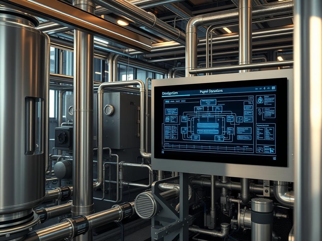
Desalination Product Water Storage serves as the strategic buffer between high-pressure membrane separation processes and the downstream distribution network. In a modern technical stack, this infrastructure functions as a massive hydraulic capacitor; it absorbs the high-frequency fluctuations of reverse osmosis production while stabilizing the low-frequency demands of municipal or industrial consumption. The primary challenge in Desalination Product Water Storage is maintaining chemical stability and biological integrity while managing a massive physical volume. This requires a sophisticated integration of mechanical engineering, chemical process control, and Industrial Internet of Things (IIoT) monitoring systems.
The solution context involves the deployment of glass-fused-to-steel or reinforced concrete reservoirs equipped with automated re-mineralization and disinfection loops. By treating the storage asset as a programmable node within a Wide Area Network (WAN), operators can mitigate the risks of demand-side latency and production-side throughput bottlenecks. This manual outlines the protocols for configuring, monitoring, and hardening these systems against mechanical failure and cyber-physical threats.
Technical Specifications
| Requirement | Operating Range | Protocol/Standard | Impact Level | Resources |
| :— | :— | :— | :— | :— |
| Hydrogen Ion Concentration | 6.5 to 8.5 pH | SM 4500-H+ B | 9 | Glass-Fused-Steel |
| Signal Communications | 10/100 Mbps | Modbus-TCP/DNP3 | 7 | CAT6a / Fiber |
| Level Monitoring | 0.1% Full Scale | 4-20mA / HART | 10 | Ultrasonic/Radar |
| Operating Temperature | 5C to 45C | IEEE 100 | 5 | Thermal Insulation |
| SCADA Integration | < 500ms Latency | OPC-UA | 8 | 8GB RAM / Quad-Core |
| Disinfection Residual | 0.2 to 2.0 mg/L | EPA 334.0 | 10 | NaOCl Dosing Pumps |
The Configuration Protocol
Environment Prerequisites:
Successful deployment requires strict adherence to AWWA D103 for steel tanks or AWWA D100 for welded structures. From a digital perspective, the integration layer requires a Linux-based gateway (Ubuntu 22.04 LTS or RHEL 9) with OpenSSL 3.0 for encrypted telemetry. All field devices, including the Programmable-Logic-Controller (PLC) and the Remote-Terminal-Unit (RTU), must support the MQTT or Modbus-TCP protocols. User permissions must follow the Principle of Least Privilege (PoLP); administrative access to the HMI-Database must be restricted to the auth_admin group.
Section A: Implementation Logic:
The engineering design of Desalination Product Water Storage focuses on the idempotent nature of hydraulic control. Every command issued by the SCADA system to a Variable-Frequency-Drive (VFD) must result in the same system state regardless of how many times it is executed, ensuring that pump surges do not induce water hammer or structural fatigue. We utilize encapsulation of sensor data into discrete digital payload packets to ensure that chemical parameters (pH, Boron, Bromide) are tracked in real-time without data corruption. The storage logic also accounts for thermal-inertia; large bodies of water resist rapid temperature changes, which can be leveraged to optimize the efficiency of the post-treatment cooling circuit.
Step-By-Step Execution
1. Initialize SCADA Node and Local Database:
Access the head-end server and execute sudo systemctl start ignition-gateway.service or the equivalent service for your specific SCADA provider. Set the initial administrative password and map the network interface to the correct VLAN for industrial traffic.
System Note: This action initializes the primary kernel threads for the polling engine. It allocates segments of memory for the real-time tag provider, ensuring that high-priority alarms for tank overflows are processed with minimal overhead.
2. Configure Modbus-TCP Gateway for Level Sensors:
Navigate to the device configuration directory at /etc/opt/modbus-gateway/conf.d/ and create a new configuration file named tank_sensors.conf. Map the Holding-Register-40001 to the ultrasonic level sensor located at the top of the reservoir.
System Note: The gateway acts as a translator between the physical sensor voltage and the digital register. By defining these registers, you enable the PLC to calculate the volume based on the tank’s geometry, providing the core data for throughput analytics.
3. Calibrate the Variable-Frequency-Drive (VFD):
Using a fluke-multimeter, verify the 4-20mA loop integrity between the PLC and the VFD-Transfer-Pump. Manually force the output to 50% via the terminal and measure the physical flow rate at the Flow-Meter-FM101.
System Note: This calibration ensures that the digital command translates accurately to physical mechanical force. Proper scaling prevents cavitation in the pump impeller, which would otherwise lead to significant signal-attenuation in the pressure sensors due to air bubbles.
4. Deploy Remineralization Control Logic:
Upload the structured text (ST) code to the PLC-Main-Controller. This logic should utilize a Proportional-Integral-Derivative (PID) loop to adjust the CO2 dosing based on the incoming pH payload from the pH-Transmitter-PHT202.
System Note: The PID loop minimizes the error between the setpoint and the actual chemical state. Use of idempotent logic here prevents over-dosing, which could lead to scaling on the interior of the Desalination Product Water Storage tank.
5. Establish Fail-Safe Physical Alerts:
Hard-wire a high-level float switch directly into the Emergency-Stop-Circuit. This bypasses the software layer entirely to ensure a physical disconnect of the fill pumps in the event of a software hang or packet-loss on the control network.
System Note: This provides a hardware-level interlock. Even if the underlying OS kernel experiences a panic, the physical asset is protected from structural failure and overflow, maintaining the integrity of the surrounding infrastructure.
Section B: Dependency Fault-Lines:
The most common mechanical bottleneck in Desalination Product Water Storage is the “Short-Circuiting” of flow, where new water exits the tank skip-passing the older, stored volume. This leads to stagnation and biological growth. On the digital side, library conflicts between Python 3.x and older SCADA drivers can cause the OPC-UA-Server to crash during high concurrency events. Ensure that all .so libraries are correctly linked in /usr/local/lib to avoid runtime execution errors.
THE TROUBLESHOOTING MATRIX
Section C: Logs & Debugging:
When diagnosing systemic failures, first check the system log using journalctl -u scada-service.service -f. Look for “Socket Timeout” or “Illegal Data Address” errors which indicate a breakdown in communication with the field sensors.
- Error Code 0x01 (Illegal Function): The RTU does not support the requested Modbus function. Verify the device manual and ensure you are not attempting to write to a read-only register at 0x30001.
- Drift in pH readings: Inspect the pH-Probe for bio-fouling. Clean with a 5% HCl solution and recalibrate using NIST-traceable buffers.
Excessive VFD Heat: Check the Thermal-Inertia settings in the motor profile. If the ramp-up time is too short, the overhead* on the electrical bus will cause a thermal trip.
- Packet-Loss at Gateway: Use tcpdump -i eth1 port 502 to analyze the traffic. If you see repeated retransmissions, check the physical shielding on the RS-485 to Ethernet converters for electromagnetic interference.
OPTIMIZATION & HARDENING
Performance Tuning:
To maximize throughput, implement a “Lead-Lag” pump rotation strategy. This distributes the mechanical wear across multiple units, reducing the risk of a single point of failure. Adjust the concurrency settings on the SCADA polling engine; by staggering the scan rates (e.g., Tank Level at 1s, Water Quality at 30s), you reduce the payload burden on the network, ensuring that critical alarms have the lowest possible latency.
Security Hardening:
Disable all unused services on the storage gateway using systemctl disable avahi-daemon. Implement a firewalld policy that only allows traffic from the specific IP addresses of the Engineering Workstation and the Primary PLC. For physical security, install tamper-evident sensors on all manway hatches and integrate these into the SCADA alarm system as high-priority “Intrusion” tags. Encrypt all field-to-cloud telemetry using TLS 1.3 to prevent man-in-the-middle attacks that could spoof tank level data.
Scaling Logic:
As the desalination plant expands, the Desalination Product Water Storage stack should scale horizontally. Add additional reservoir cells in parallel rather than increasing the height of existing ones to manage static head pressure. Use a distributed control architecture where each storage cell has its own RTU, communicating back to a central Historian-Server for long-term data logging. This modularity ensures that the failure of one node does not compromise the entire hydraulic network.
THE ADMIN DESK
Q: Why is my level sensor reporting a negative value?
A: This usually indicates a calibration offset in the 4-20mA loop. Check the Scaling-Factor in your PLC tags. If the sensor is ultrasonic, ensure no condensation is blocking the Transducer-Face, causing a false echo.
Q: How do I handle a “Communication Timeout” alarm?
A: Verify the physical connectivity of the Network-Switch. Run ping from the SCADA console to the PLC-Gateway. If packet-loss exceeds 5%, replace the shielded twisted pair cables or check for ground loops in the cabinet.
Q: What is the ideal turnover rate for stored water?
A: Aim for a complete volume turnover every 24 to 48 hours. This prevents “Dead-Zones” and minimizes the loss of disinfectant residuals, ensuring that the water remains within the mandated chemical specifications for the distribution network.
Q: Can I update the PLC firmware while the pumps are running?
A: Negative. Firmware updates require a reboot of the CPU-Module, which will drop the heartbeat signal to the VFDs. This triggers a “Fail-to-Safe” stop. Only perform updates during scheduled maintenance windows when storage is bypassed.